 |
|
THE ROTARY PARAGMA |
|
|
|
|
||||||||||||||||||||||
|
A one rotor Wankel engine is the most simple and smooth running reciprocating internal combustion engine existing today. It only has two basic moving parts. There is no reciprocating masses, except for the combustion gases, as a result of the cycling combustion chamber volume. Such an engine is running with next to no vibration except for torque fluctuations resulting from a reciprocating combustion. Power is produced in this engine like in a single cylinder two-stroke engine, one combustion for every crankshaft revolution. The basic difference is the fact that each combustion CYCLE takes three crankshaft revolutions to complete. This allowing high crankshaft RPM at a comparatively slow combustion cycle, resulting in a potential power to weight ratio comparable to the lightest known two stroke engines. With all this in mind, I decided to put more effort in realizing this engine than one would put in a normal auto engine conversion. As it turned out, it was way more than I anticipated in the early stages of the project. What engines are available from in-production hardware? I found out very quickly, that there is essentially nothing except for MAZDA with the RX7 and later RX8 sports car. As stated earlier, these engines are too big and too powerful for my application. So, take one of these engine and cut it in halve, similar to what has been done to make a 1/2 VW engine some time ago. Doing this with an RX7 engine would result in about 100hp and an acceptable weight, depending how much effort I am willing to put into modifications.
|
|
Engine Design |
|
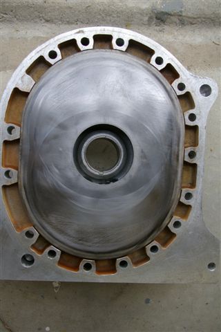
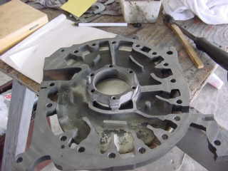
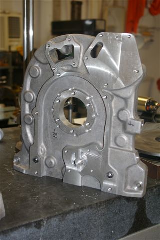
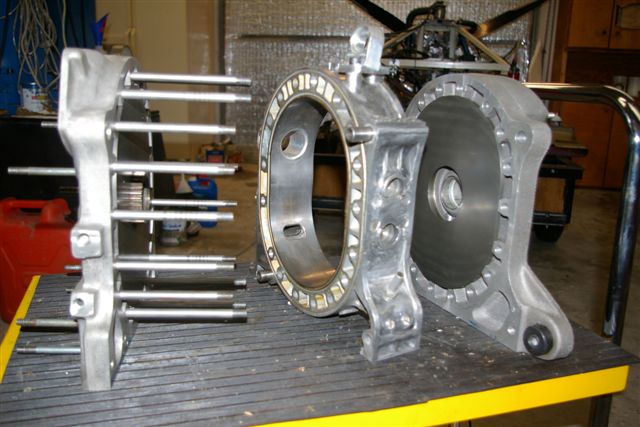
After looking at the parts of my first disassembled 12A engine, it was clear that some major parts needed to be made of aluminum rather than using the original Mazda cast iron version.Talking in particular about the side housings. The first issue coming to my mind on aluminum side housings is the wear surface. Nobody has come up with an after market aluminum side housing answering all the questions about a good wear surface at an acceptable cost. In order to keep the developmental risk manageable, I decided to retain the CI(Cast Iron) surface of the side housing. Meaning a compound housing, made up of an aluminum outer part and a CI insert as the running surface for the rotor. All aluminum casting are made of AL 356 T6. I made all the patterns and got it cast by a speciality foundry. Subsequently having to switch to a peripheral intake port, because I did not see a possibility for integrating side ports with a sound engineering solution. And, off course, as I learned later, the P-Port intake also has other advantages. The prove of principle engine made its first run in ....2001. It is running presently with the final version of the compound side housing(end of 2009). This first configuration had a peripheral port, and in addition, one side port. The side port idea was to improve low RPM idle. I immediately observed interference of the two ports at certain RPM ranges. It also turned out that on PP only, Idle around 2000 RPM was satisfactory for AC use, and I decided not to waste any time looking into the port combination any more.
|
|
|
||||||||||||||||||||||||||||||||||||||||||||||||||||||||||||||||||||||||||||||||||||||||||||||||||||||||||||||
|
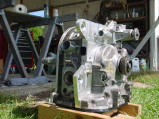
At the end of the design and development process, the only MAZDA parts left the engine, which are not modified are, the rotor, oil pump, stationary gear and some bearings. |
|
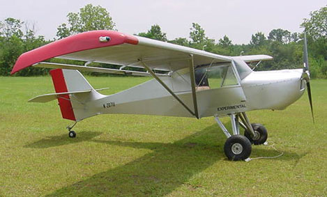
As of today, January 20 20010, the first generation design is frozen and will be installed for flight testing in the PRAGMA air plane. This should happen in the next couple of month. |
||
|
Cutting Parts. |
||
|
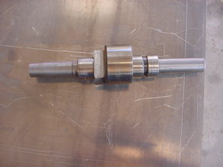
The first lesson I learned was: I can not afford getting the necessary machining work done by a machine shop. So, shelving the project? Not only nooooo... but h.... no . As a result, a gradual building up of machining capability was essential for the success of the project. Starting out with making an excenter shaft was like jumping in a swimming pool at 35F. But it worked out pretty well for the prove-of-principle engine.
Finally, by the end of 2008, my machine shop was joint by a CNC milling capability, making things possible I was only dreaming off a few years ago.
|
|
|
||||||||||||||||||||
|
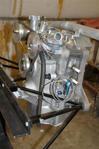
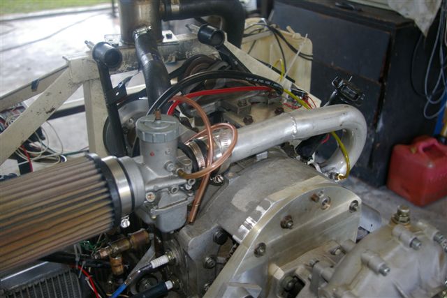
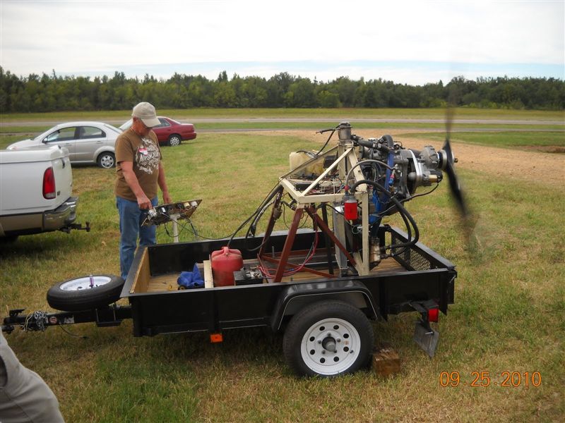
The reason for this was the location of the breather pickup on the engine. I had it on the oil filler, which is on top of the accessory housing. Apparently, the oil is just too much in motion and foaming in this area for this solution. Hooking the breather up to a fitting in the oil pan, just below the anti-foam plate solved the problem. The engine is now running very solid at 6000RPM and WOT. Calculated HP is 92 - 100 , depending on the BSFC No. using. Demonstration run at Alternative Engine Gathering in Paducah, KY, 2010. Picture by Douglas Dempsy.
In my personal view, it is already more power than I need for flying the PRAGMA. Configuration Overview. Engine size 1/2 MAXDA 12A Excenter shaft Modified 12A with case hardened bearings and 10:1 taper output. Flywheel Custom design with integrated balance weight. Oil pump MAZDA 12A Water pump Subaru Alternator 30A PM. Ignition Streetfire CDI , dual coil Carburetion AeroV Injector.
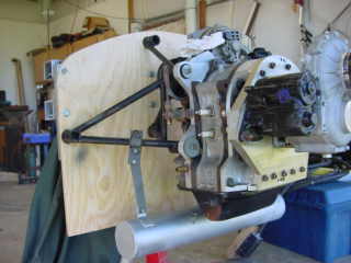
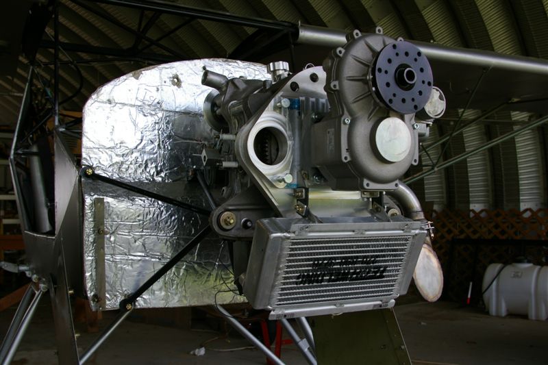
Moving into the area of airplane installation presented a bucket full of new challenges. Some of these are still cooking now. For a motor mount, I choose a 3-point version, with 2 Hard points and one tension strut. A nice feature on the AVID is, it has six hard points on the fuselage for mounting the engine. Unfortunately two of those were in the wrong location for a practical rotary engine mount. With that corrected, the motor mount turned out pretty decent.
|
|
|
||||||||||||||||||||||||||||||||||||||||||||||||||||||||||||||||||||||||||||||||||||||||||||||||||||||||||||||||||||||||||||