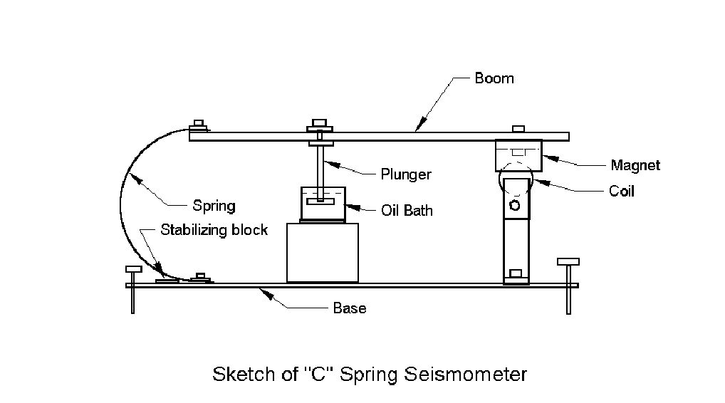
The “C” Spring Seismometer
This seismometer
has all the parts common to every seismometer including damper and
spring. What is unusual is the elimination of a moving
hinge and associated friction and noise.
Except for the springs, the
structural materials are aluminum to prevent magnetic
interactions.
Wood could also be used but would bring potential problems with
moisture and swelling, and the resulting need to change the
adjustments frequently.
Here is a brief description of components:
Frame
A single flat piece of aluminum ¼
inch by 4 inches by 24 inches is used as the base and frame.
Three holes are drilled into the base and threaded for use as support
legs and leveling adjustment. Additional holes are
drilled and threaded for mounting the springs (hacksaw blades) and coil
support.
It is important to use a non-magnetic
material for the base to prevent difficult interactions with the
sensor magnet which will be mounted on the boom.
Boom
The
boom is a ½ inch square aluminum tube 24 inches long.
This also must be non-magnetic to prevent interactions with the
magnet. Two threaded holes and one clean hole will be made in
this
member. The damper will be clamped to the
boom.
Springs
Two hacksaw blades are used for
the springs. The blades must be sufficiently flexible to allow
bending them into a half circle. Longer springs are
better so use the longest hacksaw blade available. Band saw
blades could also be used.
Used blades would work equally well
as new blades. It is important to grind the teeth from
the blades to allow for a smooth bending throughout the length of the
spring. With the teeth in place, the blade has a
non-uniform width which results in a concentration of stress at the
root of each tooth.
Caution! The springs have considerable stored energy and could cause injury if broken or accidentally released. Stay away from the probable path of the broken or accidentally released parts.
Coil and magnet
The coil and
magnet must be matched to ensure that the coil will mesh with the
magnet. A horseshoe magnet is pictured but a speaker magnet
could be used with appropriate mounting changes. The coil can
be taken from a 120V-240V relay.
Most seismic
amplifiers are high impedance devices so the coil should have as many
turns as possible. 120V-240V relay coils typically
have more turns than coils from automotive relays and are
preferred.
Some builders prefer to place the magnet on the
base and coil on the boom. This has the advantage of reducing
local magnetic disturbance of the boom, but the disadvantage of more
complex construction.
Damper
A damper is necessary to prevent energy from the first seismic wave from carrying over to later waves. A oil damper is used because of the simplicity of this method. A choice can be made between a simple flat plunger or the more complicated vane assembly. The vane damper will allow a wider frequency response which included higher frequency waves desired at this location.
The flat damper can be made from a 1 inch diameter washer.
Drill holes in the washer to improve the higher frequency
response.
The vane washer can be made from thin material such as copper or a
tinned material taken from food cans. The plates can be assembled
parallel by placing removable cardboard spacers between each plate
before soldering in place. A vane 1 inch by 1 inch by 1 inch
worked well for the pictured seismometer.
The viscosity of the oil is adjusted to control the damping. Under damping allows energy from one cycle to carry over into the next cycle. Over damping decreases the sensitivity of the instrument. Test for correct damping by displacing and then releasing the boom. The trace from a correctly damped boom will return to the zero position with a small overshoot. The pictured seismometer is slightly over damped with the trace returning with no overshoot.
Assembly
The
springs made from hacksaw blades are clamped to the base and boom
under 1/8 inch by 1 inch flat strips about 3 inches long. The
blades are spaced 2 inches apart center to center.
The damper
is clamped onto the boom to allow for easy adjustment laterally along
the boom. The damper is placed about in the middle of the
boom but placement is not critical.
The magnet is bolted as
far out on the boom as possible while meeting the goal of a
horizontal boom.
Stabilizing blocks
Cut two 1/8
inch by 1 inch by 1 inch blocks. These will be used to
stabilize the boom which will be unable to find a stable position
when the springs are clamped parallel on a flat base. Stability
will come when
we place these blocks on the base but under each spring so that the
outside edge of each spring is slightly higher than the inside
edge.
Each spring then has a “bias” toward the center and
stability is easily achieved.
The pinching effect from the springs is enough to hold the
stabilizing blocks in place. No further attaching of the
blocks to the base is needed.
Adjustment
Adjustment
is easy. First, make make the coil support height correct to
allow the coil to mesh with the magnet when the boom is parallel
with the
base.
Place the instrument on a suitable surface and adjust
the base screws to make the base level.
Make very rough
adjustments by sliding the magnet and damper along the boom
(while the damper is NOT in the oil bath) until a horizontal beam
position is obtained. Adjust the stability blocks
interactively with the magnet and damper.
When a stable
position is found with the boom level, add the oil bath assembly and
insert the damper plunger. The boom will float higher so
the damper will need to be moved further out (away from the springs)
on the boom.
Final adjustment is made with the base
adjusting screws. Be sure that the coil does not contact the
magnet. The smallest link between the two part, even if as
small as a spider thread, will destroy the sensitivity of the
instrument.
Results
The instrument is
sufficiently sensitive to see small earthquakes riding on the
microseims caused by ocean wave action and observable worldwide.
Sensitive drops off below about 0.2 Hertz. The period of the
pictured seismometer is between 5 and 6 seconds.
Long term
stability is good. Expect to adjust the instrument within a few
days as all the parts settle in to a stable configuration. Once
stable, the instrument will go for months without needing adjustment.
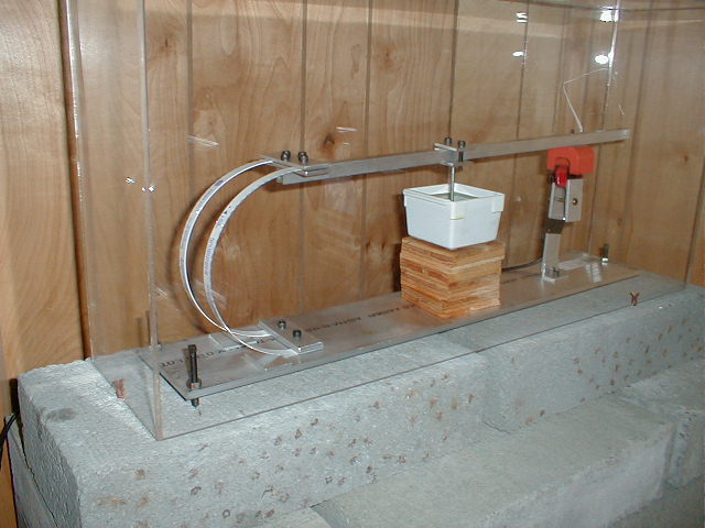
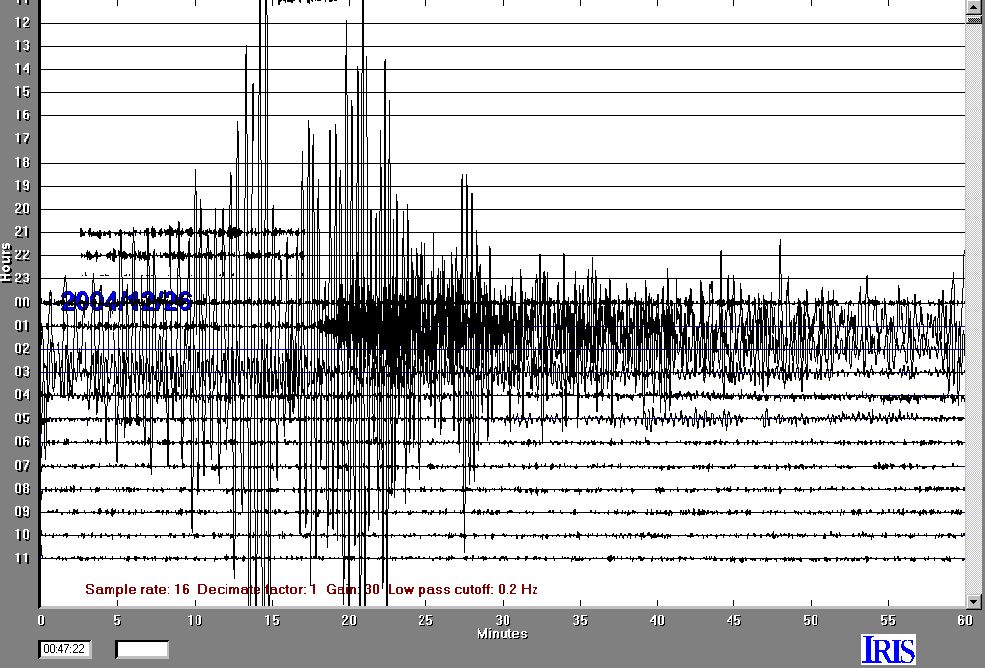
This recording of the December 26, 2004 Sumatra magnitude 9.0
quake was detected with the instrument in the photo at the top of the
page. The signal was amplified with the Saum
A/D conversion/amplifier board and recorded with Amaseis software.
Click here for the photo of the
"C" Spring Seismometer.
Click here for the image of
the Sumatra Quake recorded with the "C" Spring Seismometer.
September 15, 2005
rsparks@elltel.net